The growing stakes of electronic thermal management
Modern ICs and power-dense PCBs chew through ever-larger current densities, and every extra watt of heat they dissipate multiplies the mechanical stress that solder joints, die attach, under-fill, and encapsulant must endure. Thermal testing of electronics, therefore, sits on the critical path between design sign-off and volume shipment: it proves that devices can survive both the slow “office-lifetime” drift of junction temperature and the violent expansion/contraction caused by fast thermal excursions in the field. Reliability studies show that temperature cycling can trigger delamination, wire-bond lift, and micro-cracks long before electrical overstress becomes visible, making thermal validation the single most predictive screen for latent failure modes in semiconductors and sensor assemblies. For OEMs and fabless companies alike, skipping or abbreviating thermal tests is no longer an option—the cost of an automotive recall or datacenter outage dwarfs the investment in a dedicated temperature forcing system. As silicon geometries shrink to 3 nm and gate-all-around structures hit production, allowable delta-T between core and case is tighter than ever; meanwhile, AI accelerators, radar/LiDAR chips, and GaN power stages must pass qualification across −40 °C … +150 °C. These trends make electronic thermal management not just a PCB-level concern but a boardroom KPI, and they also explain the steep rise in search interest for tools that can impose, measure, and log controlled temperature profiles with pinpoint repeatability. Sysmetric Thermal Forcing Systems
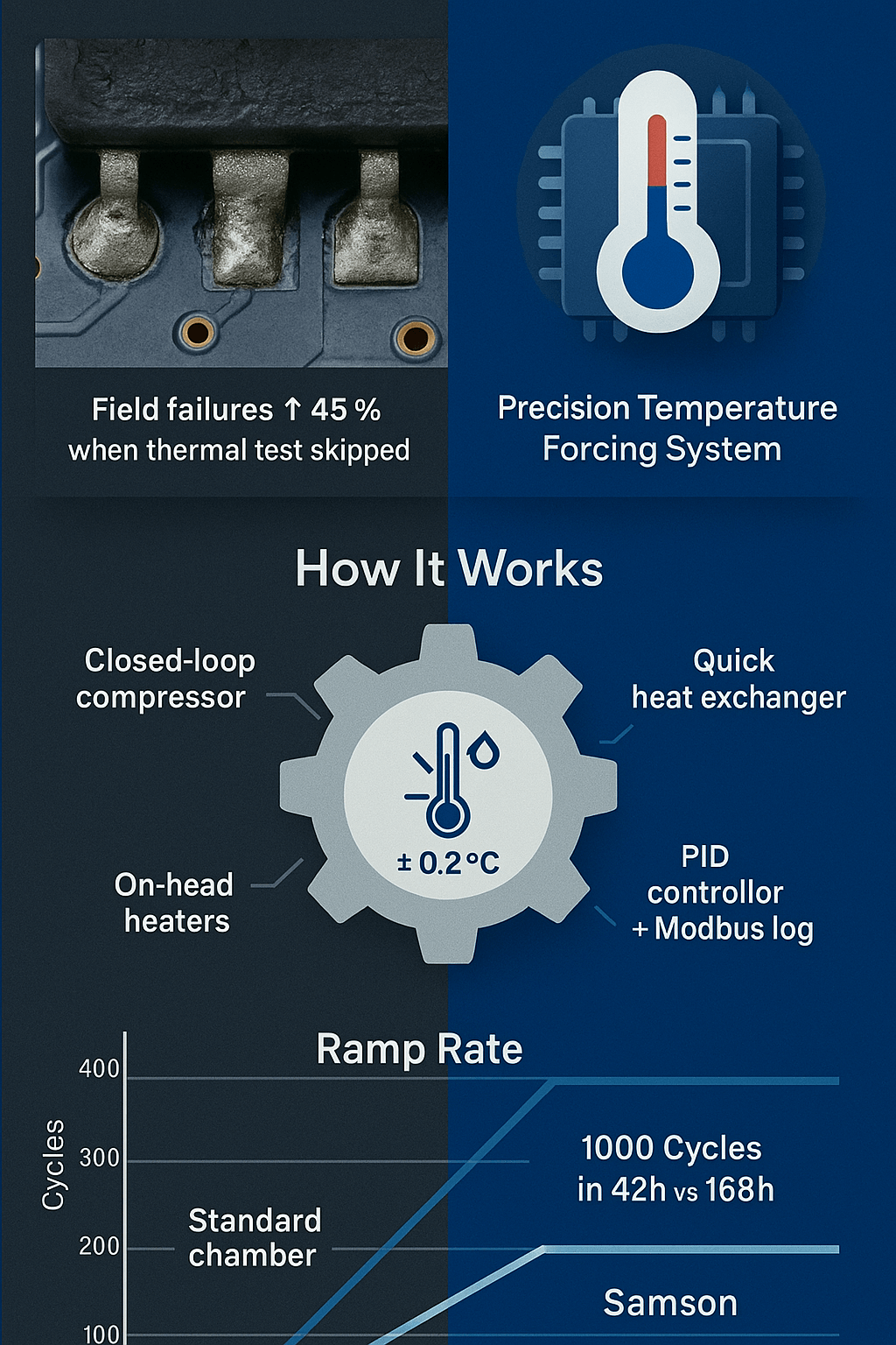
How a temperature forcing system works (and why a quick heat exchanger makes it faster)
At the heart of every laboratory-class precision temperature forcing system is a closed vapor-compression or Peltier cascade that pumps heat into—or out of—the device under test (DUT) through a removable thermal head. Sysmetric-TFS’s flagship Samson platform, for instance, clamps directly onto Intel’s Six-Shot racks and swings the DUT from −40 °C to +120 °C with a ±0.2 °C control tolerance. A miniature refrigerant circuit (R452A) feeds the cold plate while a proportional PID loop modulates heater cartridges, yielding a hot/cold ramp rate of roughly 1 °C s⁻¹ unloaded and sustaining 600 W at 0 °C when loaded. Inside the head, a quick heat exchanger of low-volume copper micro-channels strips or injects heat faster than conventional serpentine blocks, minimising soak time and avoiding condensation thanks to an air-purge envelope. Because the thermal core is only 78 × 86 mm and the umbilical is 2.3 m long, engineers can slip the probe into dense SLT (system-level test) racks or ATE nests without redesigning fixtures.
Q | What range should a thermal test chamber cover for ICs?
For most JEDEC, AEC-Q100 and military standards the envelope is at least −55 °C … +125 °C; high-reliability aerospace and down-hole tools extend this to −65 °C … +200 °C. The Samson, combined with Sysmetric’s Artic desktop chamber, easily satisfies the mainstream automotive and consumer corner cases while larger dual-stage systems such as the ThermoJet reach −80 °C … +225 °C for flight-grade parts.
Q | How does a temperature forcing system work?
The controller senses the DUT case via a high-speed thermocouple, predicts the required enthalpy change and commands the compressor (or TEC array) plus on-head heaters to swing toward the next set-point. A rapid-response heat-exchanger spreads the flux evenly so neither bond wires nor MIM caps see hotspots. All parameters—ramp rate, soak time, dwell cycles—are logged over I²C or Modbus to the host for correlation with functional test vectors. Sysmetric Thermal Forcing SystemsScientific ProductsTop Quick Cooling
3. Rapid temperature-cycling: the most telling reliability screen
Why is thermal cycling critical for semiconductor reliability? Every join in a packaged device—die-attach epoxy, copper pillar, solder ball, even mould compound—possesses a unique coefficient of thermal expansion (CTE). Repeated excursions between cold soak and hot soak mismatch those CTEs and load the interfaces in shear; microscopic fatigue accumulates until the resistance of the inter-connect jumps or the encapsulant cracks. Temperature cycling therefore accelerates ageing mechanisms that would otherwise take years to surface in the customer’s product. The latest rapid temperature cycling test equipment for electronics compresses a 1 000-cycle AEC-Q100 Gr. 2 profile into a weekend shift by hitting ramp slopes of 15 °C s⁻¹ (air-stream) or 40 °C s⁻¹ (liquid-immersion). Data published by Caplinq confirms that even a modest 5 °C min⁻¹ gradient can induce delamination in BGAs that sailed through electrical burn-in, underlining the complementarity of the two screens.
Sysmetric-TFS couples its Samson tools with desktop programmable chambers so QA teams can combine board-level humidity-bias, HALT vibration, and thermal characterisation without juggling vendors. The DUT identifier, time-stamp, and environmental metadata are pushed via Python APIs straight into the PLM system, letting quality engineers overlay log-normal lifetime predictions on Weibull plots in real-time. In SLT bays, the same head indexes serially across sockets, cutting change-over to seconds and raising utilisation beyond 90 %. By front-loading reliability discovery in the lab, design houses shave weeks off the silicon bring-up schedule and avoid the dreaded ECO loops that wipe out product margins. Thermal testing cycle vs shock
4. From post-silicon validation to road-worthy electronics
Automotive OEMs now guarantee ADAS domain controllers for a 15-year lifecycle and a −40 °C … +150 °C mission profile—numbers that dwarf the old infotainment spec. Consequently, boards undergo not only functional drive-cycle tests but also service-level thermal testing services for automotive electronics reliability. Sysmetric-TFS answers this need with a rack-mount “Car-Industry Solution” variant whose head seals around odd-form LiDAR or radar assemblies while allowing full 360-degree rotation of the sensor during the test. Engineers script deterministic ramps (e.g., +25 °C → +125 °C at 10 °C min⁻¹, dwell 30 min, −40 °C soak) directly from CAN, LIN or Ethernet-AVB harnesses, pulling live performance counters over the same bus to correlate thermal drift with ranging accuracy or signal-to-noise ratio.
Q | What is thermal validation in electronics?
It is the structured process of applying controlled temperature stimuli to a powered-on DUT while verifying that all target specifications—functional, timing, analogue fidelity, RF noise, power integrity—remain within guard-bands. A complete plan covers pre-silicon thermal simulation (FEM), post-silicon validation on socket-level instruments and finally system-level validation (SLV) in assembled ECUs or modules. Fail-first-time metrics from the thermal station feed DFMEA loops, triggering metal-mask fixes or package optimisations long before SOP. Because road-worthiness standards (ISO 26262, JESD22-A104, VW 80100) penalise latent faults harshly, many Tier-1s now specify not just number of cycles but maximum allowed temperature gradient and soak uniformity—KPIs a precision temperature forcing system documents automatically. Sysmetric Thermal Forcing Systems
5. Cost, pilot programmes and the business case
Budgets remain tight, so procurement teams scrutinise any cap-ex request for a new lab instrument. The good news is that Sysmetric-TFS positions its Samson and Artic families aggressively: entry configurations start well below the six-figure threshold traditionally associated with legacy chillers and thermal shock chambers, and the company invites prospects to run a “try-before-you-buy” precision temperature forcing system price and pilot program. Customers ship a sacrificial DUT panel and a test script; Sysmetric returns a full thermal profile, log files and video, along with a quote calibrated to the exact cooling-power envelope required—no overshoot, no hidden options. Because a single unscheduled line-stop can cost a fab many times the instrument price, ROI typically closes in under three months. Further savings accrue from the unit’s low energy draw (air-cooled variants plug into a 230 V / 15 A circuit) and from its field-swappable condenser cartridges, which cut mean-time-to-repair by 70 %. The vendor’s Python library drops into existing pytest or LabVIEW stacks, so there is no middleware tax, and the on-head purge cycle extends tool life by preventing ice build-up on the cold tip. Internal-link tip: use the anchor text “precision temperature forcing system” when linking this paragraph to Sysmetric’s product page to strengthen topical authority around the phrase. Sysmetric Thermal Forcing
6. Implementation checklist and speed benchmarks
Deploying a temperature station is straightforward if you follow three rules:
(1) isolate the DUT thermocouple from probe-card heaters,
(2) keep hose bends above a 20 cm radius to guarantee refrigerant flow
(3) script defrost routines for any profile that dips below dew-point.
How fast can temperature forcing systems ramp? The Samson posts 1 °C s⁻¹ without load, translating to a −40 °C ↔ +120 °C swing in roughly three minutes; high-end airstream units such as the ThermoJet reach a +200 °C → −65 °C transition in under 15 s for small footprints. Selecting the right tool is thus a trade-off between ramp speed, DUT mass and chamber-free workspace.