Samson+ (Neptune)
Phase Change Thermal Forcing System
Operation Manual
Neptune
Revision: June 2025

1. Introduction
The new cooling/heating forcing system is targeted to answer customers’ demands to validate Si components in temperature ranges of -55ºC up to +150ºC in a cooling/heating envelope between 350W@-40ºC to 200W@0ºC and 1300 watt @ 140ºc. The Samson+/Neptune thermal tool was designed to fit specific dimensions to fit into Intel Six Shot rack ( 30x30x550cm). The tool thermal head is designed to fit pneumatical force actuation up to 200 Kg and gimbaling with minimum KOV (Keep Out Volume).
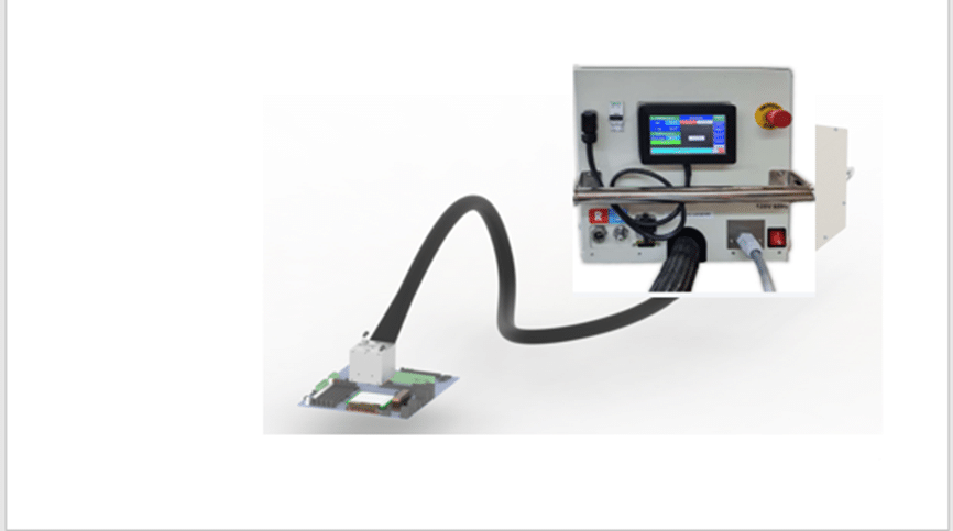
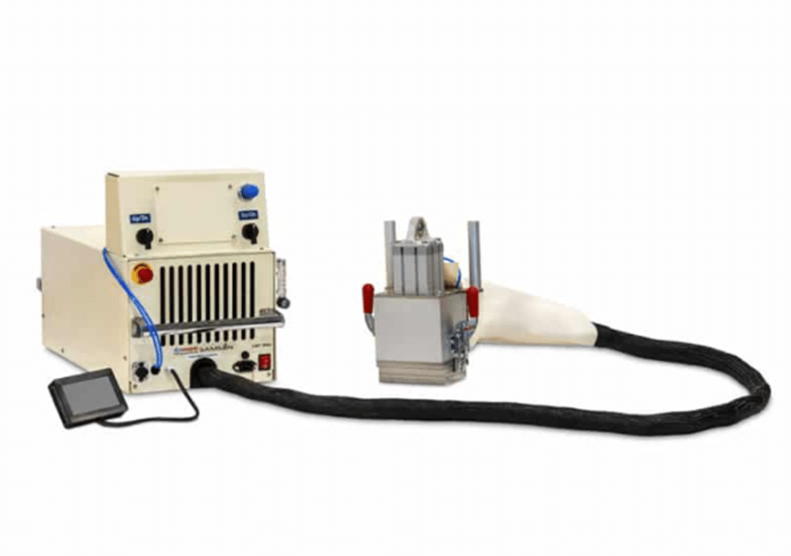
Samson + with clamping device:
- Samson+ is refered to 3 ph power supply.
- Neptune is refred to 230v 60Hz power supply.
Samson with Clamp:
1.1 Standard Features
- Samson+/Neptune comes in three configurations:
- Neptune Water (PCW liquid cooling) 3liter@15ºc 230 volt 60 Hz.
- Neptune Water (PCW liquid cooling) 3liter@15ºc 230 volt 50 Hz.
- Samson+ Water (PCW liquid cooling) 3liter@15ºc 3 Phase 440v -480v 50/60Hz +Ground + natural. Phase to Phase is 480Volts. The system is indefrence in the phase order. The Delta -Y onnection is internal and has no relevance.
- Cooling power envelope of the tool is 350W@-40ºC (Tc) and 1200W@0ºC (Tc) with 10mm pedestal Highet.
- Temperature range -56ºC to +150ºC.
- Temperature change rate (hot/cold) is approximately 1.4ºC/sec (without load).
- Temperature control ±0.2ºC from Set Point.
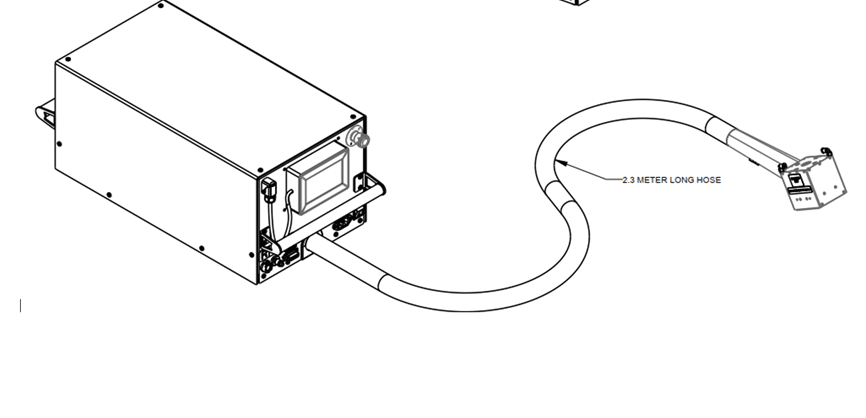
- The hose length between the thermal head and the control box is 230cm (220cm for the first models).
- Remote interface: option 1; using I2C comm’ protocol is specifically designed to support InTEC controller. option 2; TCP over UDP w/ python lib both can work with Static-ip or DHCP.
- Defrost system activates below 20ºC.
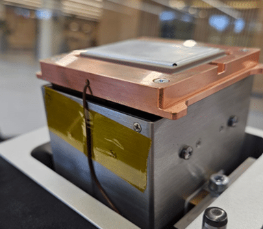
- Dry Air purge is avilaible with Thermal head size 70x70m.
1.2 Hazards
- Each thermal tool is specifically designed to be powered by either of the following sources:
- 230V 50Hz. 6A during operation.
- 230V 60Hz max. 6A during operation.
- 3 Phase 440V and max 4A during operation.
- All control sub-systems and wiring use 24Volt DC.
- Internal refrigerant system contains pressurized refrigerant R452A.
- All pressurized system parts comply to commercial piping industry standards.
1.3 Safety Features
- The operation of this device should be by authorized personnel only.
- The Samson+/Naptune tool intended be installed in a rack or a table.
- All system components comply to CE standards. See appendix A. MSDS for SUVA® R452A Refrigerant gas is used for cooling.
- https://www.fsw.uk.com/sites/www.fsw.uk.com/files/r452a_sds_0.pdf
- https://www.honeywell-refrigerants.com/europe/wp-content/uploads/2017/10/Solstice-452A-UK-english-1.pdf
- Maximum internal pressure is 15 Bar. Refrigerant weight is 300gr.
- The tool will power off when its thermal head temperature reaches 150ºC, or internal water leak detected.
- For Samson+/Neptune In case of leak detection, the main water valve will close, and the tool will power off.
- Intel InTEC controller will turn the Neptune thermal tool off at 130ºC.
1.4 Safety Symbols
Below are examples of safety symbols and their meanings. They appear on certain tool parts.
1. Caution – risk of electric shock

2. Ground – connect power supply ground wire here

3. Hot/ Cold – Tool thermal head surface can reach very cold and very hot temperatures. Be aware before touching the thermal head during operation.
! Temperatures can reach -40⁰C and +125⁰C
1.5 Facilities Requirements
- The Neptune should be powered through a circuit breaker used as the main overcurrent protection device and main disconnection device. A circuit breaker rated 230V, 16A or 120V, 20A (be aware in rush current for 120V 60 can be up to 50 amps) So wires supply need to be:
- 230V 50Hz (inrush up to 30 Amp) and max. 6A during operation.
- 230V 60Hz (inrush up to 50 Amp) and max. 6A during operation.
- 3 phase 440 volt 40/60Hz (inrush up to 25 Amp) and max. 3.5A during operation.
- System Type: 480/277v
- Lile to line voltage :480v
- Line to natural Voltage: 277v
- Note :Industrial lighting and Motors.
- Dry Air requirements max 4 litter/min due point -80ºc.
- Water supply : 2.8 -3.2 lite/minute at 15ºc cooling capacity at least 1.5kw @ 15ºc.
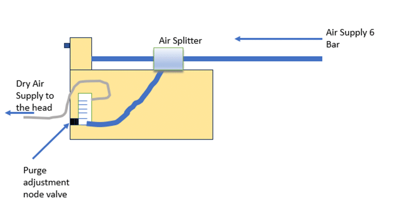
- Regular Air Supply 6 bar 8mm hose diameter to support thermal head pneumatics.
- Neptune Water Chiller tool requires a standard 208-230V 50Hz or 3Phase 480V 60Hz outlet only, depending on a tool specification. PCW with a flow rate of 3.2±0.2 Litter/per Minute and a temperature of 15⁰C.
- Dry Air Flow recommended up to 2 liter per / min due point -80ºc
- Total cooling system efficiency is ~55%.
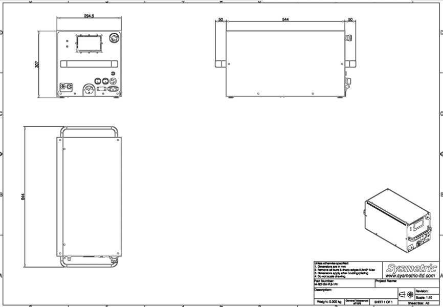
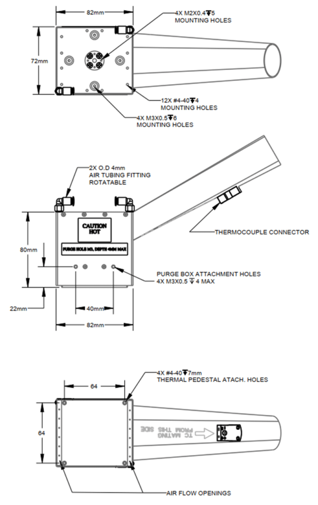
2. General Dimensions
See Appendix B
3. Before You Start
- Make sure that the tool thermal head doesn’t interfere with environment and the tool hose is not bent with a minimum radius of 20cm (7.9in) to allow free flow.
- The next 4 points points are relevant to intel equipment only!
- Verify that the InTEC cable (a gray cable) is securely connected to the tool control box
- Verify that the InTEC cable (a gray cable) is connected to InTEC – while InTEC itself is not switched on.
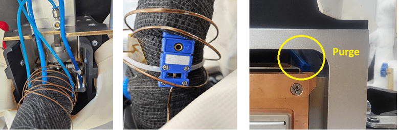
- Verify the TC (Thermocouple) connector is connected to its mating connector on InTEC
- Mount the tool UI LCD on any ferrous surface (Six Shot rack side wall or a cart side). For Neptune Water tool the UI LCD can be left attached to the tool control box.
- Verify the TC (Thermocouple) connector ,male is mounted to the blue famale conector along the main hose for T-case measurement and is well mounted to the pedestal
- Caution: Before connecting a power cord to the tool, verify the electricity voltage and frequency match both on a tool spec and a power outlet. The power requirements are written on a tool side identification panel. Power outlet options:
- Option 1: 230V 50Hz, 8A MIN
- Option 2: 120V 60 Hz, 16A MIN
- Option 3: 3 phase 440/400 volt as specified above.
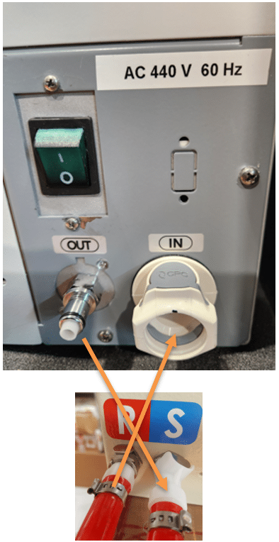
- For Neptune Water tool, connect the PCW supply and return hoses. PCW supply is marked with “S”. PCW return is marked with “R”.
Neptune Water tool Supply and Return hoses connection:

If u used a chiller from Bonn Cooling be aware connect the Chiller hoses the correct directions:
- Chiller OUT goes to Neptune S (Supply)
- Chiller IN goes to Neptune R ( Return to chiller)
4. Tool Operation
Basic operation
CLAMP OPERTION
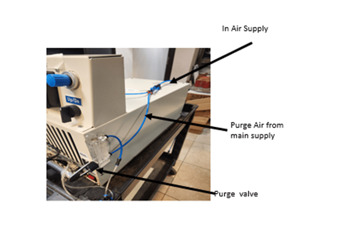
Clamp Air connection schematic:
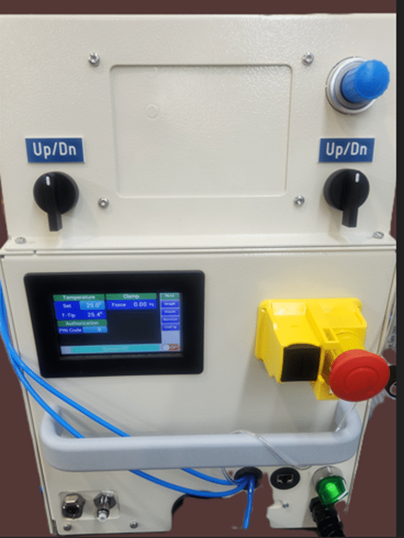
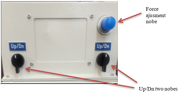
Clamp Control panel:
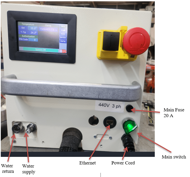
Samson + front panel:
- Plug in the 3ph connector as described above.
- Switch the tool to “ON” by moving the green switch to the right green light shoud be show and the main LCD will be displayed.
- Tap “Main” in the upper right corner of the UI LCD.
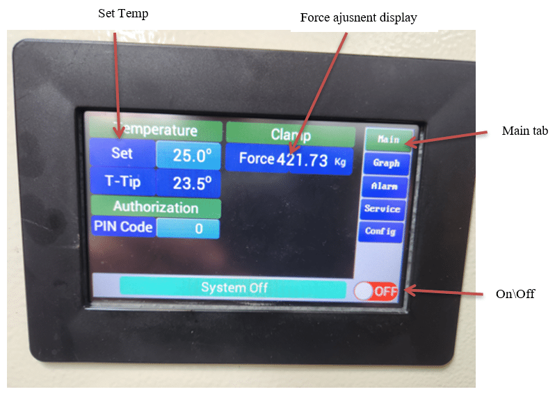
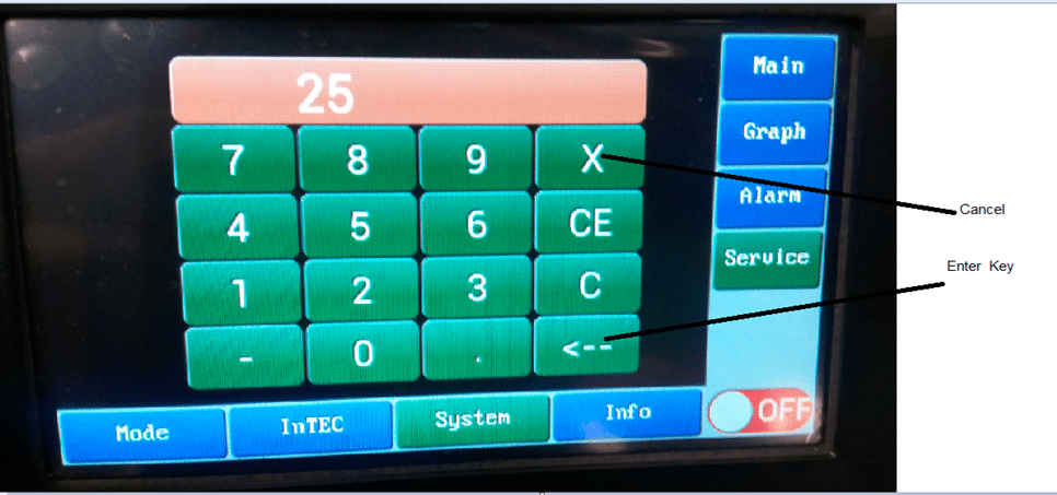
- Make sure temperature Set Point is set to 25ºC, if not tap the temperature value next to the Set and change to 25ºC. Tap the Enter Key (left arrow) to enter the new temperature.
- Turn on the tool by tapping the “OFF” button on the UI LCD, after a few seconds (up to 30 seconds) the tool status will change to green indicating that it is ON.
- Wait at least 5 minutes until pressure and the four tips temperatures stabilize (25ºC).
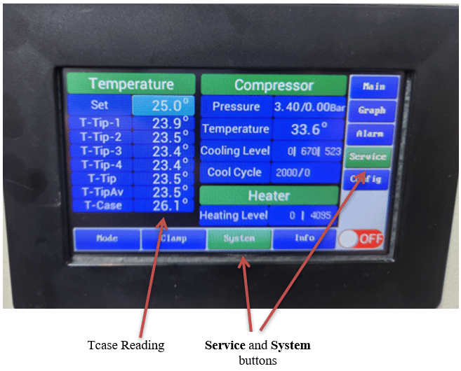
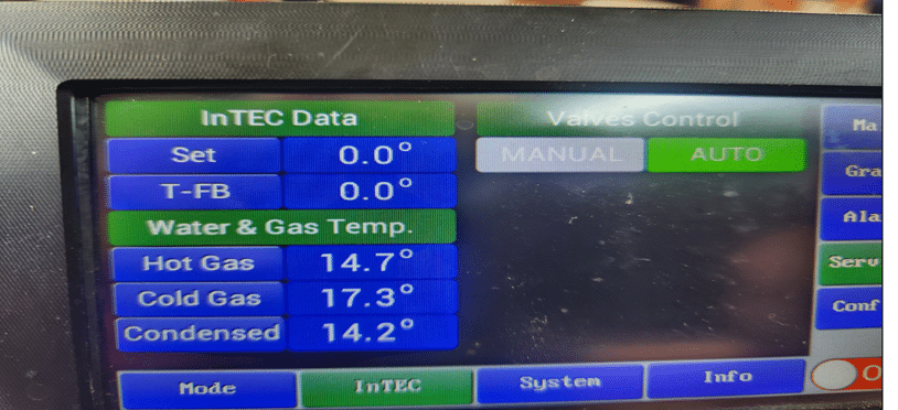
- In order to view system parameters, enter the service screen by tapping Service and then System:
Mode screen:
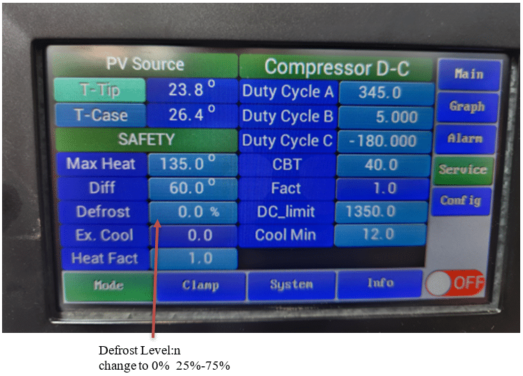
In the Mode screen a user is able to change the defrost heating level at rate 0%, 25%, 50%, 75% and 100%. The default should be set to 75%.
There are other parameters in this screen, but their values should be changed only by a qualified maintenance personnel.
Caution: only a qualified maintenance personnel should modify these parameters as system operation and performance can be affected with an improper use.
InTEC Screen:
Intec screen will indicates Hot Gas con.
If Hot gas will raise above 60ºc alarm will be triggered – meaning water supply is not sufficient – should be in Temp range of 20-60ºc and flow of 3 Liter per minute.
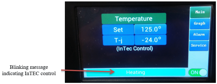
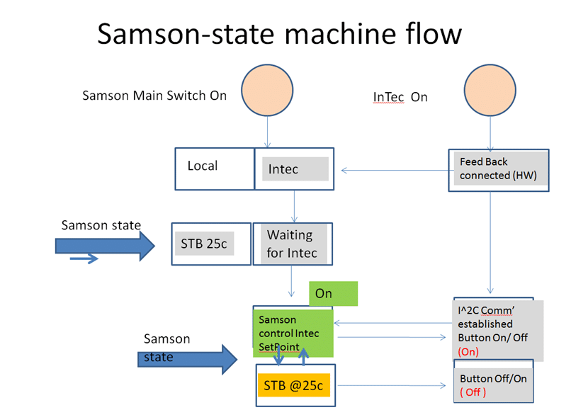
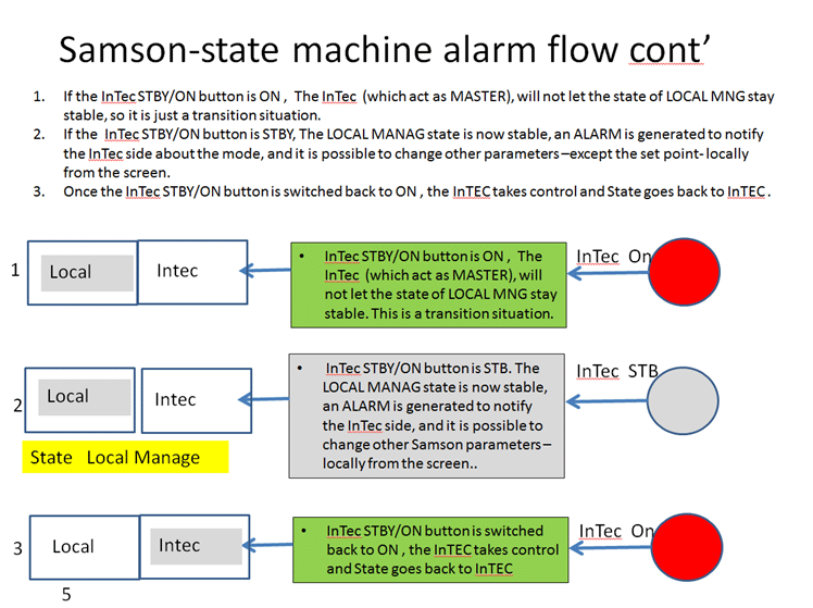
5. InTEC Connection
- Verify the InTEC cable is connected both to the Neptune and to the InTEC.
- Turn the InTEC power switch on.
- After several seconds a message “Intec Control” will blink on the Neptune UI LCD indicating that InTEC controls the Neptune tool now.
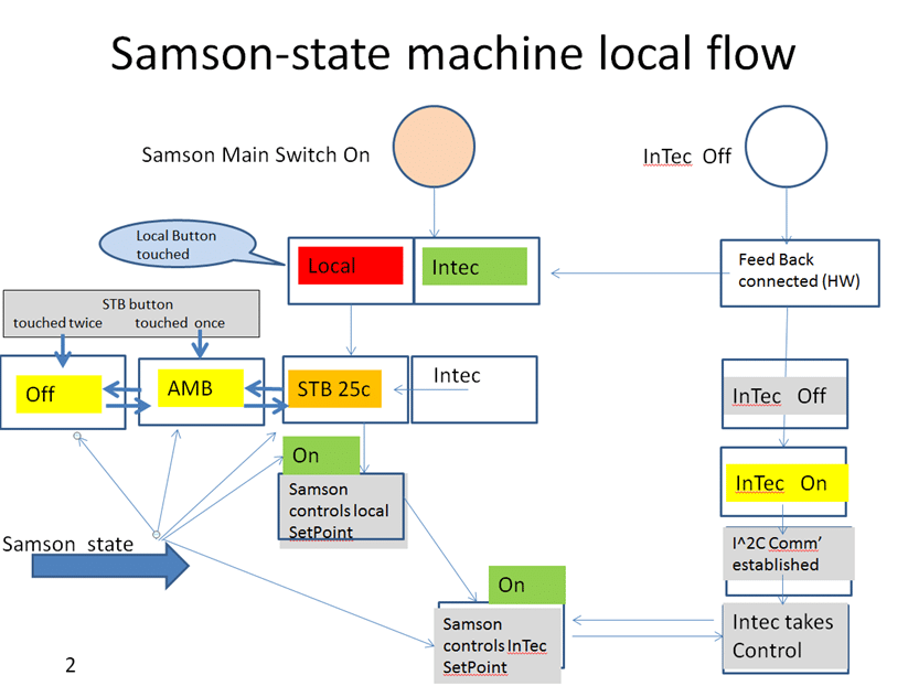
Note: None of the Neptune tool parameters can be changed while InTEC controls the Neptune tool. In order to change the Neptune tool parameters, the tool should be changed to a LOCAL mode.
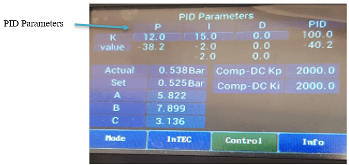
6. PID Parameters, Advanced Options
The PID values can be modified from Service -> Control screen
The PID values are to be used only by qualified maintenance personnel.
Caution: only a qualified maintenance personnel should modify these parameters as system operation and performance can be affected with an improper use.
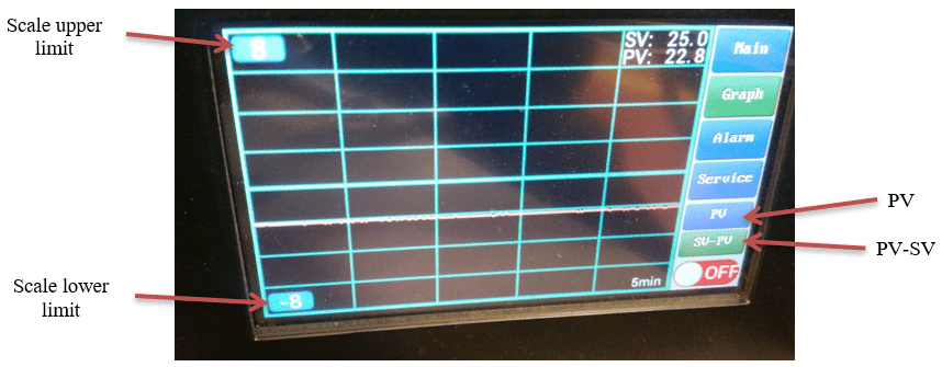
7. Graph View
In order to see the Temperature Graph tap Graph on the main screen.
There are 2 parameters to view the graph:
- PV – Process Value
- SV – Set Value
PV- SV button displays the delta between process value and setting value.
PV button displays the actual temperature.
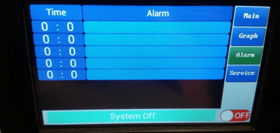
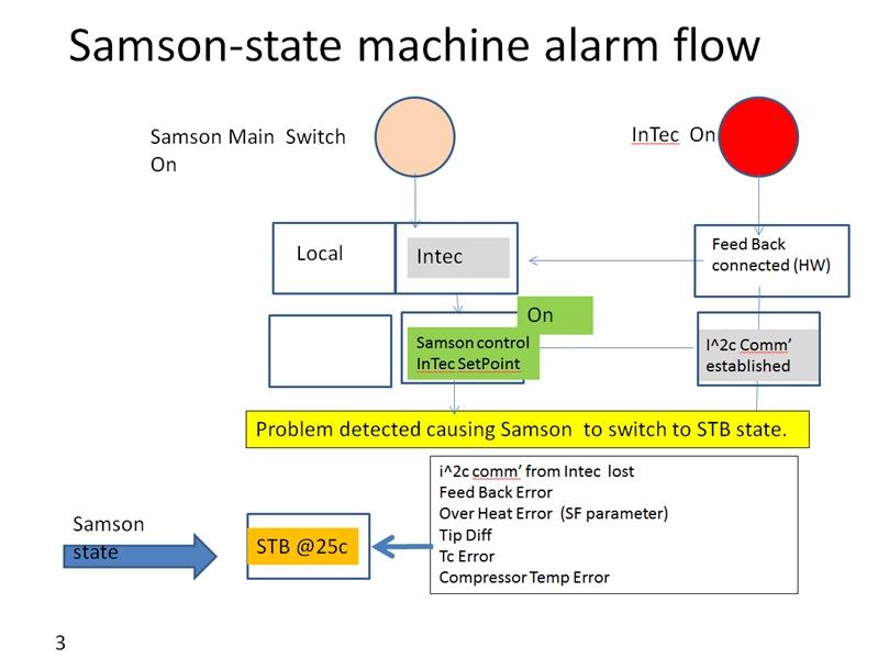
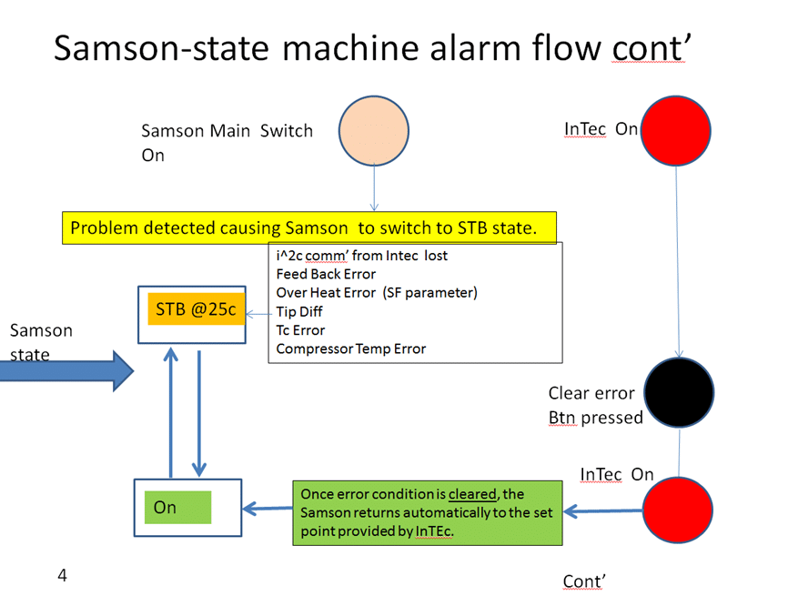
8. Alarms
Alarm screen logs alarm events during operation. All alarms are transmitted to the InTEC controller (if connected). example alarms messages: I2C communication error, High temp, Low compressor pressure, Tip temp difference.
A critical alarm will shut down the machine: a thermal head temperature reaches 140ºC, a cooling fan is not functioning properly, water leak detected, a compressor temperature reaches above 70ºC (Neptune Air), a condenser temperature reaches above 70 ºC (Neptune Water).
9. Firmware
The Neptune tool comes with the latest available firmware straight from the factory. However, firmware updates are being released from time to time. To update the tool firmware, connect an ethernet cable to the RG-45 connector which is located on a front panel of the Neptune control box.
For firmware update procedure see Appendix C.
10. Thermal Kit (Pedestal) Mounting
The thermal pedestal should be assembled following provided procedures. Use gloves.
- Make sure that Samson surface is clean: push out Samson main piston like showing in the picture.
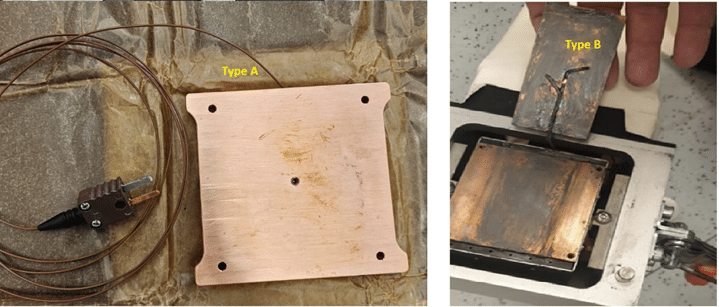
- Verify that you receive correct pedestal and it compatible with your product.
- Verify that you have correct thermocouple.
- Make sure that thermocouple is attached well to pedestal.
- Put a thermal grease (thin layer) on Samson surface. Use Thermal grease that compitable to your product.
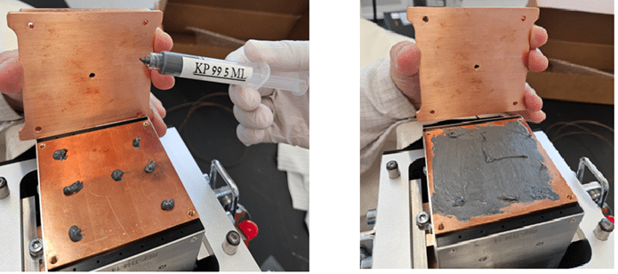
- Attach pedestal and lock it with screws. After you press on a device at first time, tighten the screws again. And clead up any grease residure.
- Connect the thermocouple to the Samson outlet. Make sure that cable passing smoothly and does not interfere with the movement of the main piston.
- Performe UP/DOWN tests and make sure that movement is smooth.
- Set purge pressure for your product request.
11. Maintenance
A Neptune tool should be Service for inspection and maintenance every 2 years. The inspection includes checkups for leak detection, valves operation and a compressor operation. For more information please contact Neptune tool Intel product manager.
Appendix A
Appendix B
Neptune Water control box:
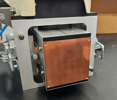
A thermal head: This thermal head comes with both Neptune Air and Neptune Water tools.
Appendix C – Firmware Update
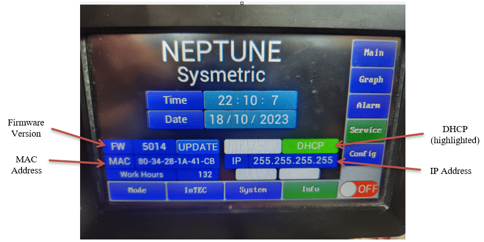
Tap Service -> Info in lower right screen, the following screen appears:
- Make sure the tool is in “OFF” mode.
- Download “LMFlash Programmer” software to a local PC from the following link (downloading firmware to Neptune can be carried out on a PC with DHCP/DIRECT link configuration). LM Programmer Link: http://www.ti.com/tool/LMFLASHPROGRAMMER (Must use build 1613).
- Make sure that the needed firmware ‘*.bin’ file is available on you PC.
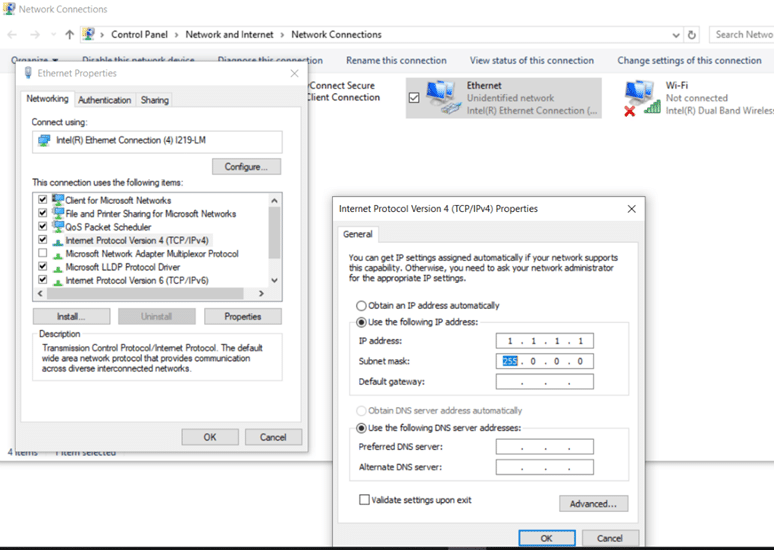
- Disconnect Wi-Fi on your PC and change Internet Protocol Version 4 (TCP/IPv4) to use a specific IP (see the below picture).
- Connect LAN cable between the PC and the Neptune tool.
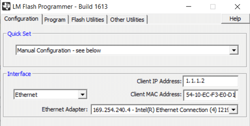
- Open the LM FLASH.exe
- Configure Quick Set to Manual configuration and then set Client IP address to 1.1.1.2 and Client MAC address to tactual Neptune MAC address (to see the MAC address navigate to Service -> Info)
- From the Program menu browse to the needed directory to select the FW file.
- From the Neptune main screen change InTec to Local then touch turn off on the tool UI LCD to put a tool in a turned off mode.
- In UI LCD Navigate to Service -> Info to change the IP to Static IP and update IP to1.1.1.2.
- Go to LM Flash and press “program”. It should take several seconds to have the new firmware “burned”.
- On Neptune UI LCD there will “Firmware Update” message.
- The tool will restart. Go to Service -> Info and check the firmware version to display the installed version.